Saw's Blog Saw's Blog
Real-time Image Filtering using FPGA
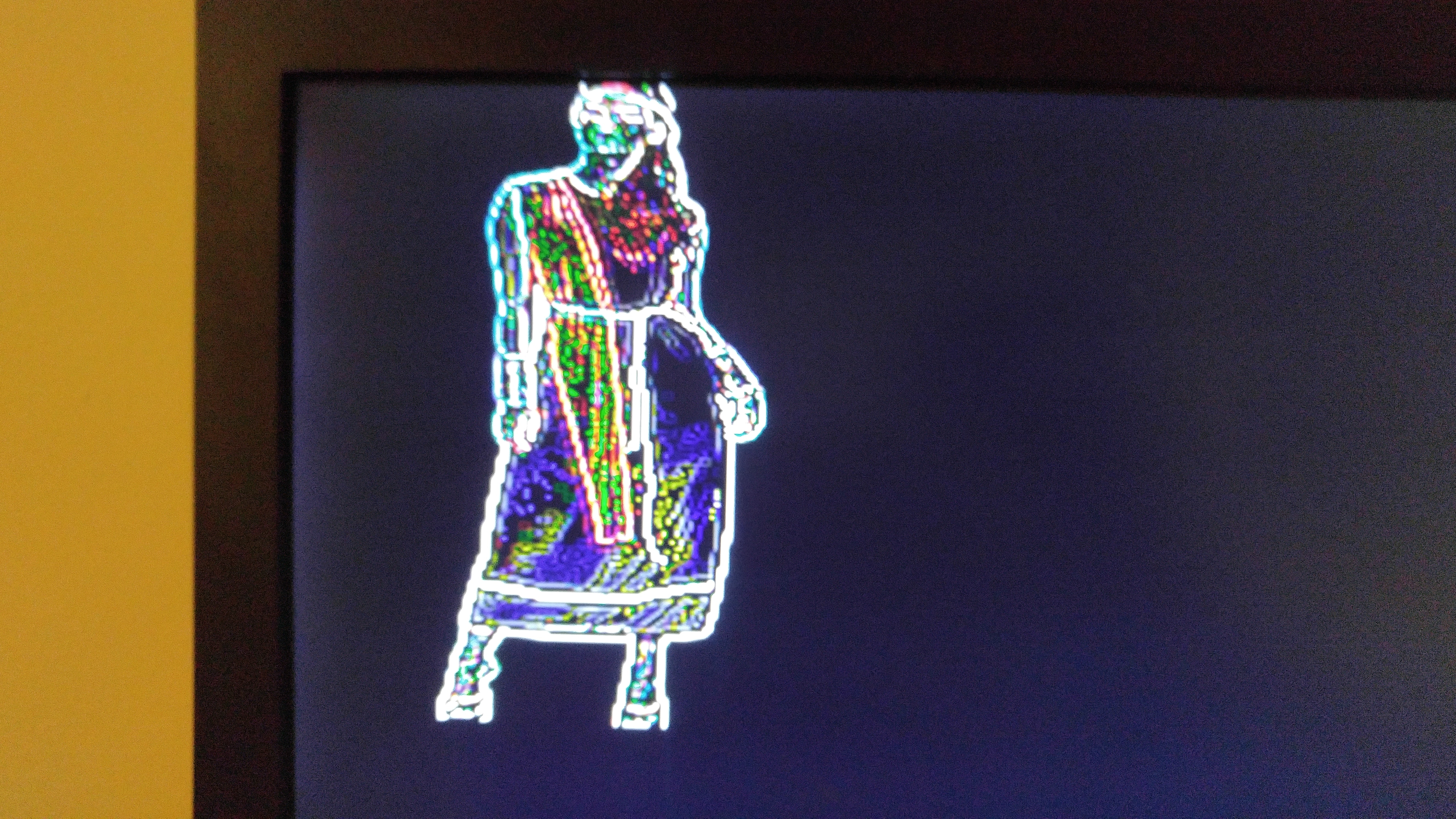
During my undergraduate years in Penn State, one of the project I have worked on is using FPGA to do an image processing at real time. The goal of the project was to feed in video stream from a camera and be able to do edge filtering with it at real time. My motivation for this project was two fold: one, I’ve read some articles online that there were some delay issues with performing image processing at the application level and two, I was extremely interested in computer vision at the time. Anyhow, this is the results of the project.
Results
Repository: Github
Because the path delay of the DSP-components easily exceeds the timing contraints, a finite state machine was used to pipeline the 2D-convolution process.
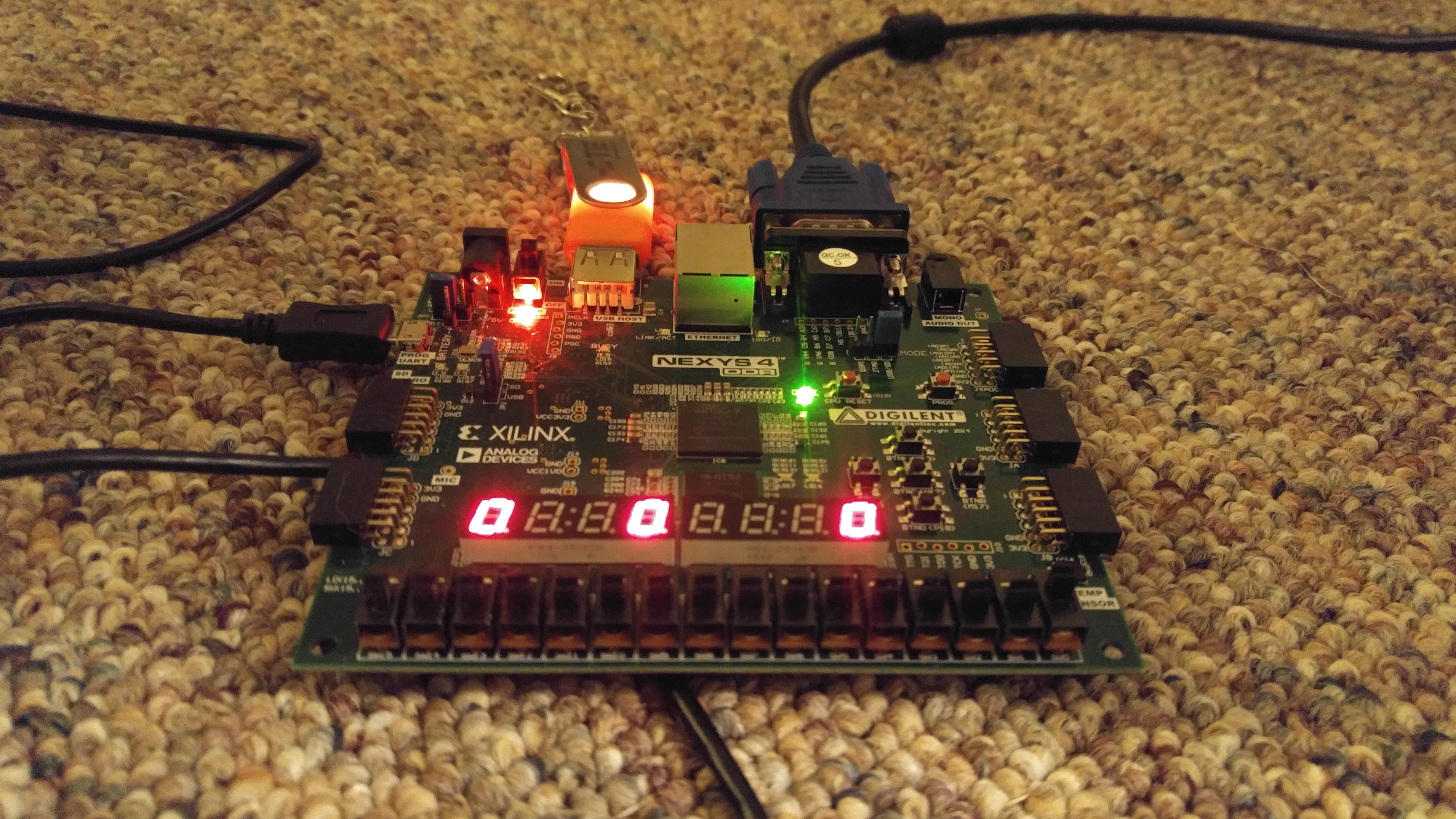
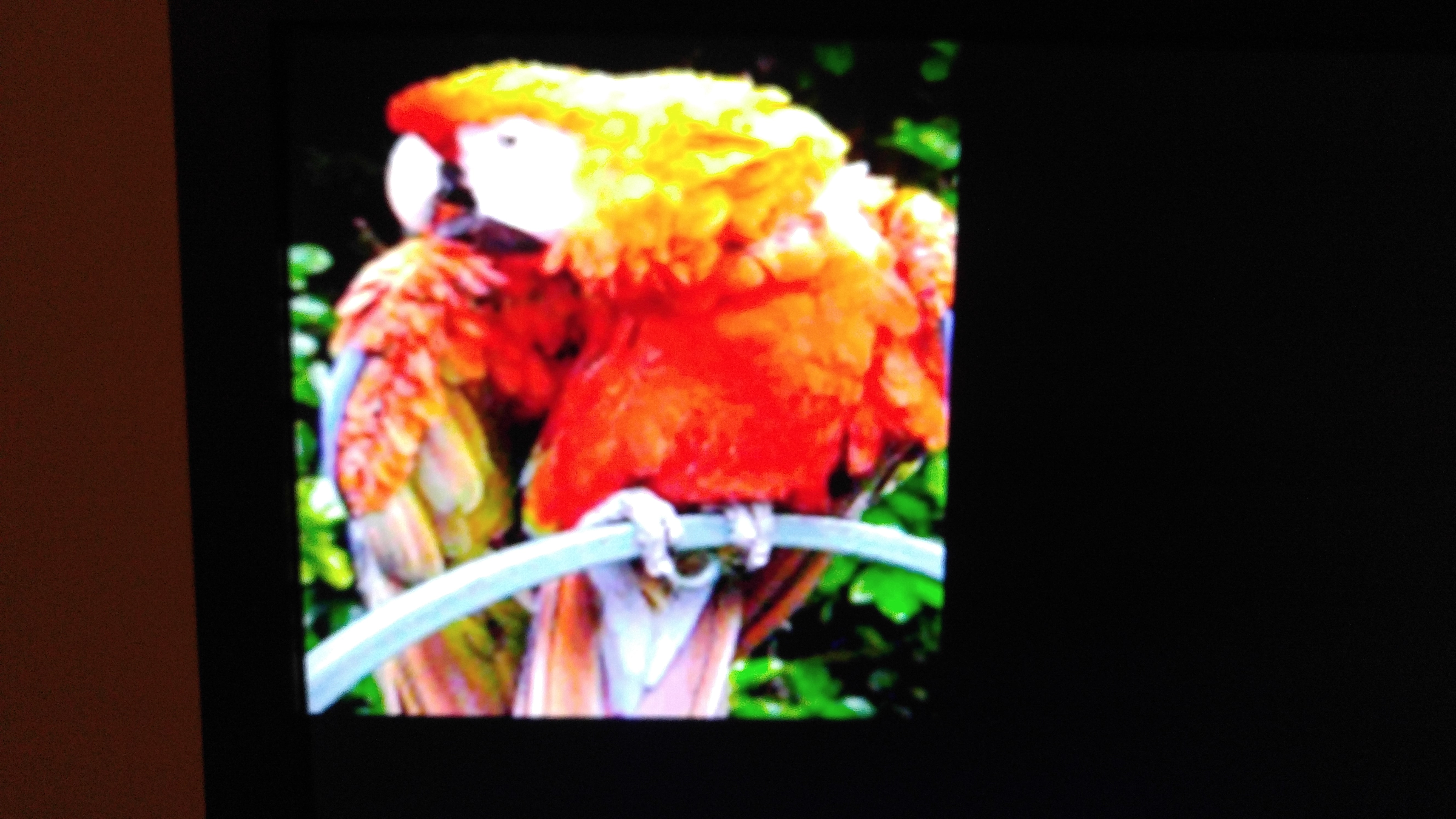
The base images (girl and parrot) are loaded into seperate ram blocks. A 12-bit bus width is used for the ram due to the 12-bits VGA RGB ports of the Nexys4 board. A depth of 30000 is used to store a 200x150 px image.
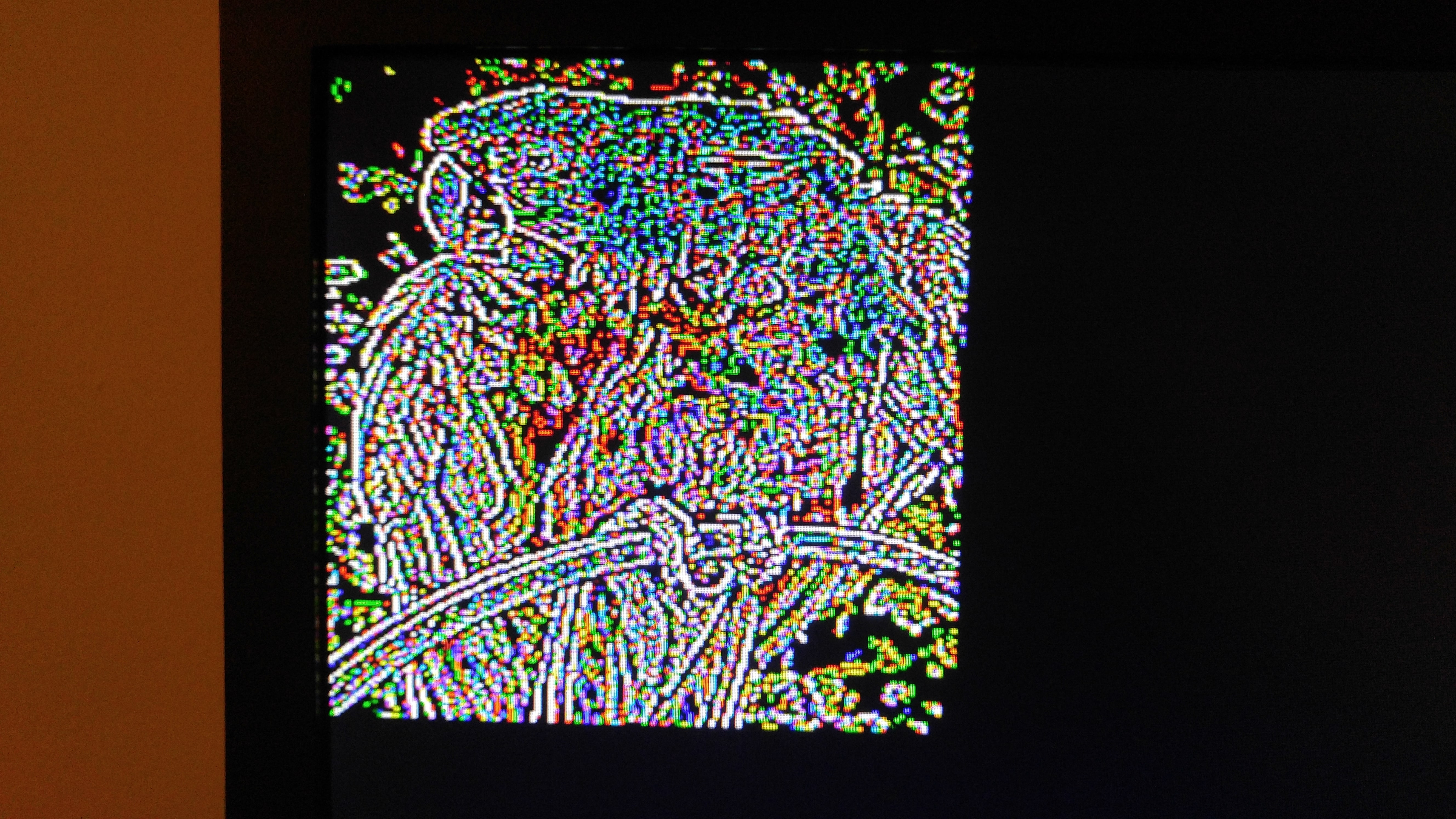
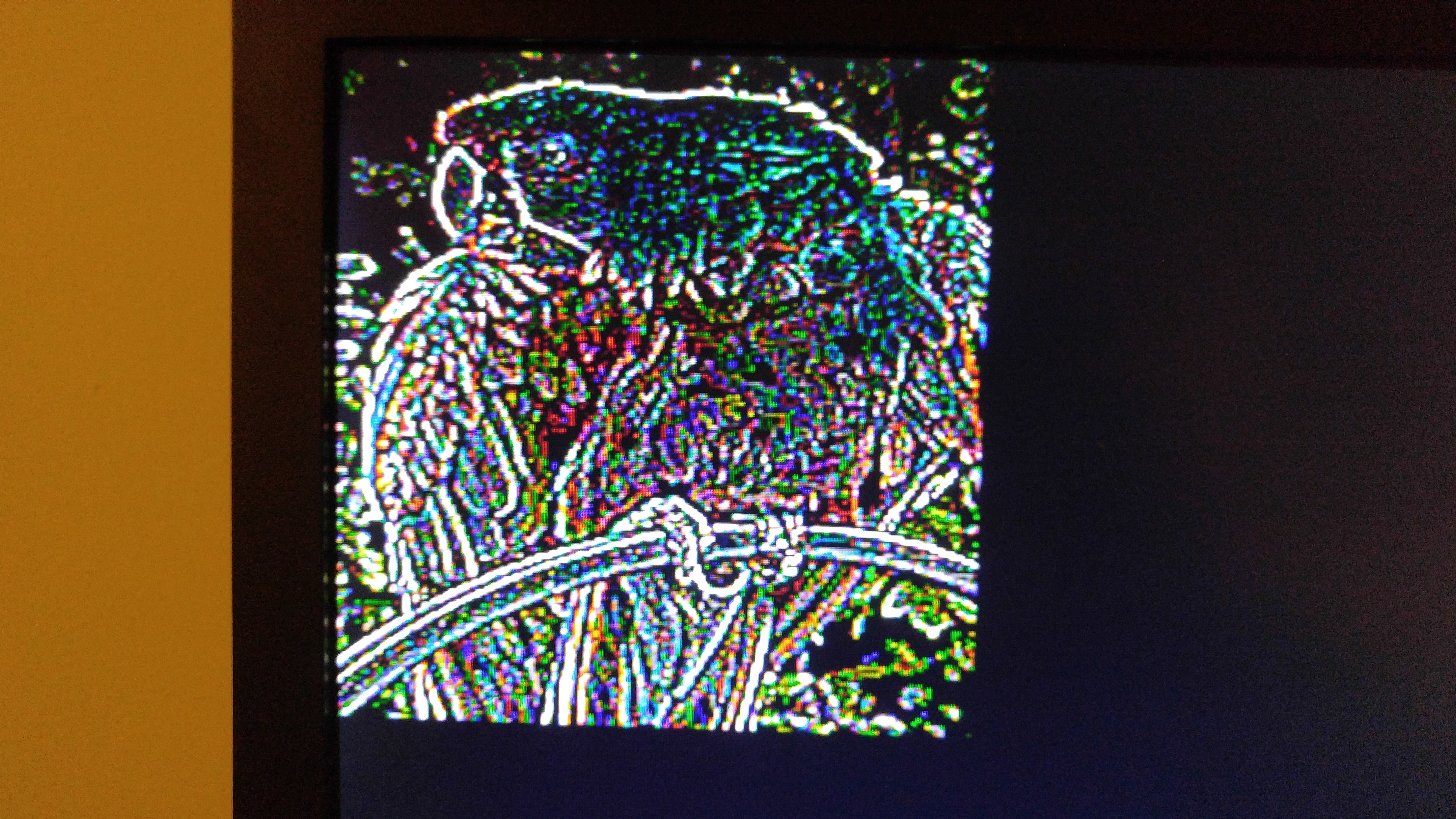
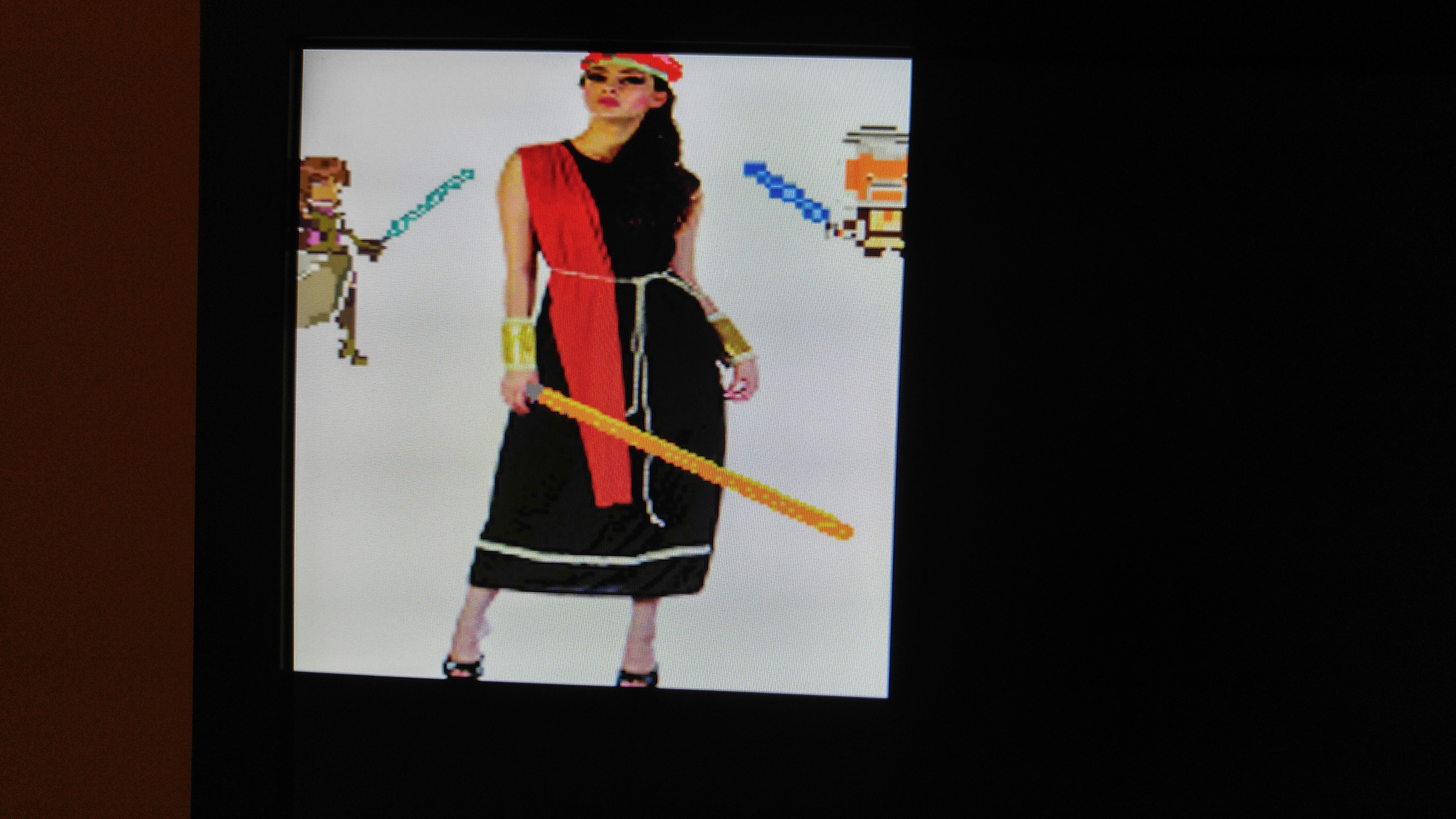
Several filters such as edge-filter, sobel, gaussian blur, emboss are implemented. They can be selected using the switches located at the bottom of the board. From right to left, the seven segment digit shows which filter the 1st stage is using, which filter the 2nd stage is using, and which image the two filter is applied on.
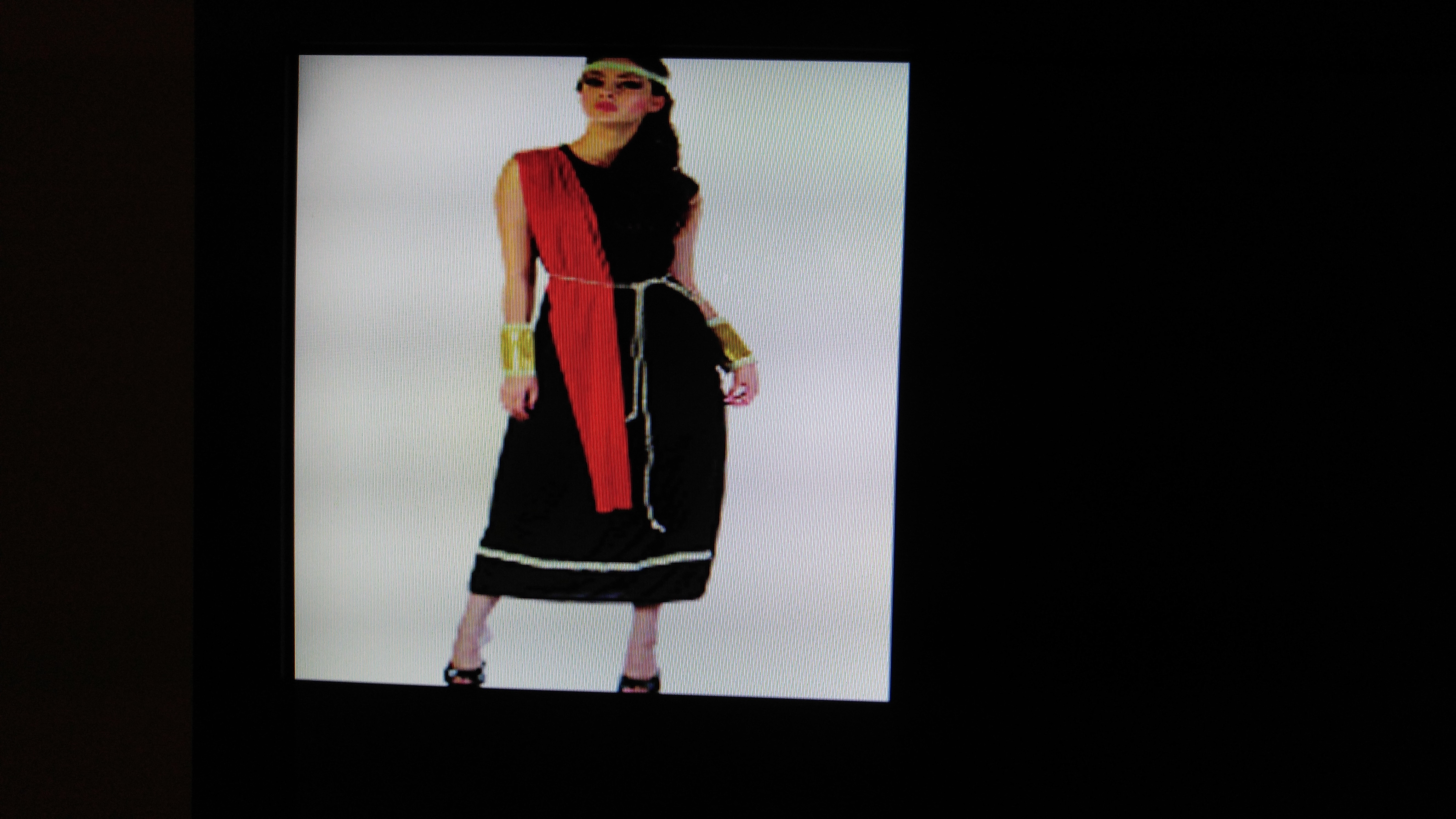

With overlay image. Easily implemented by simply using a few AND and OR gates.
See https://en.wikipedia.org/wiki/Mask_(computing)#Image_masks
Implementaion details
Here I have included the diagrams that I thought are important to understand the implementations of the project. There are specific things like datapath of the controller units, and actual top level implementation that are left out, but those can be easily understood by going over the VHDL codes.
Top Level Explained
The image below shows the Top Level overview of the filter implementation. The entire process is fairly straightforward. From the left, the diagram shows the Image being serialized from hardcoded rom, shifted into the kernel filter for processing. The output is then loaded into a buffer and starts another filtering process and finally is outputted in VGA format.
A buffer is not needed but is utilized to simplify the process of two stages filtering. For example, the filters can be implemented directly to filter twice as the pixels are accumulated. The complexity involved, however, may be too much and impractical to implement.
As a seperate functionality, an additionaly image stored in rom can also be overlaid on top of the rom images by performing some simple operations. The details can be read here
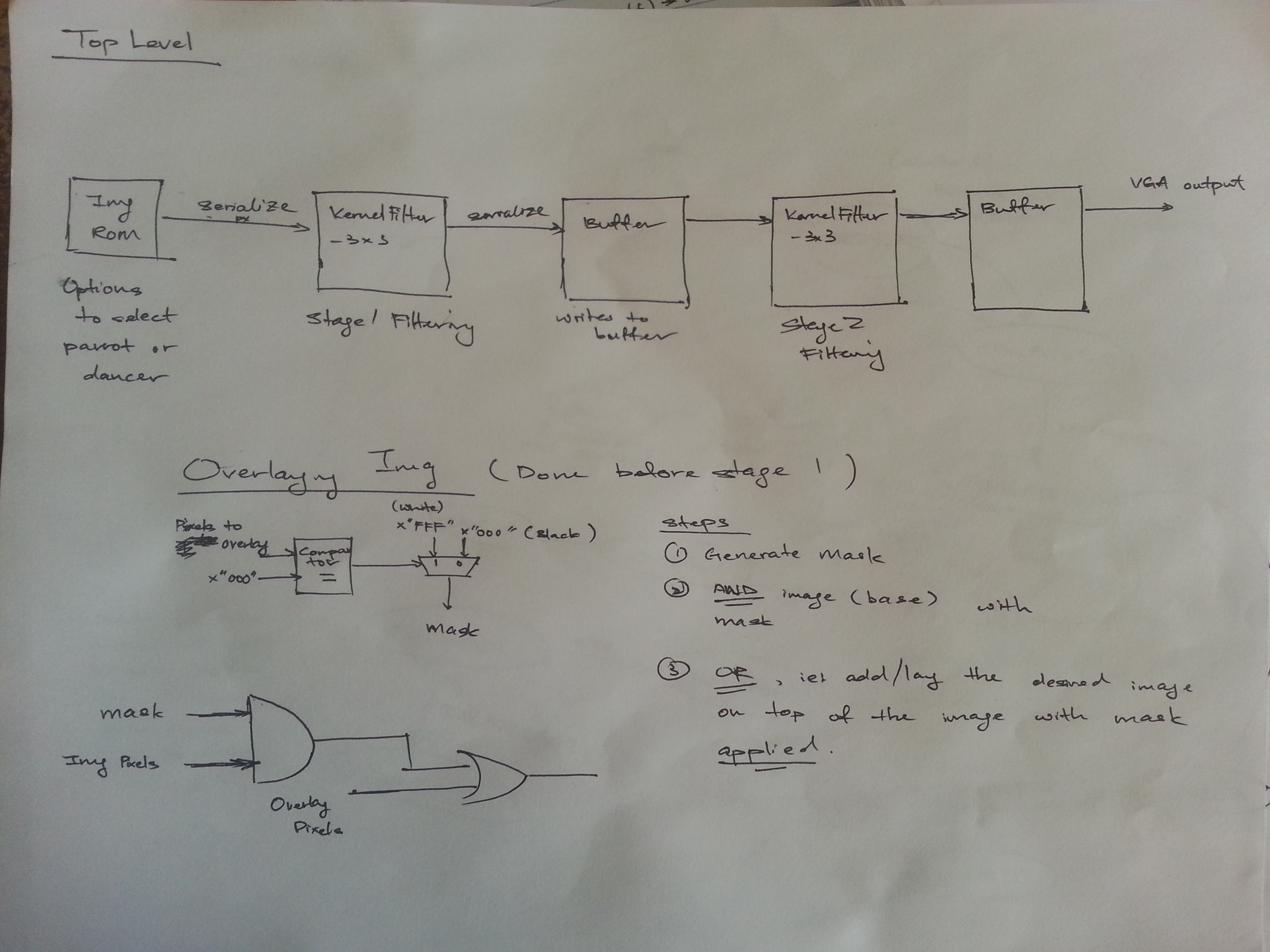
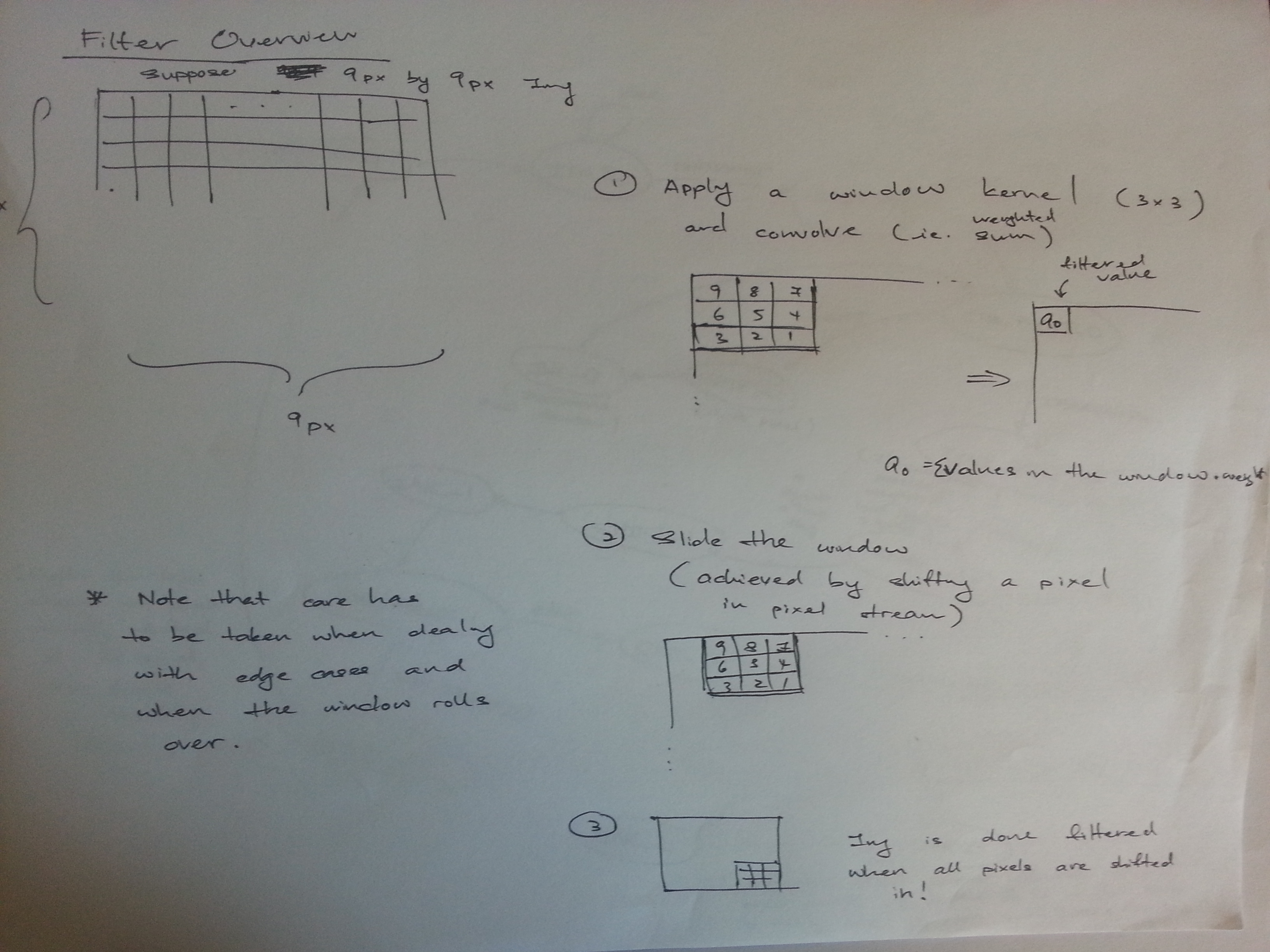
Image Filtering Implementation Explained
The three images below shows the implementation behind the sliding window image filtering method.
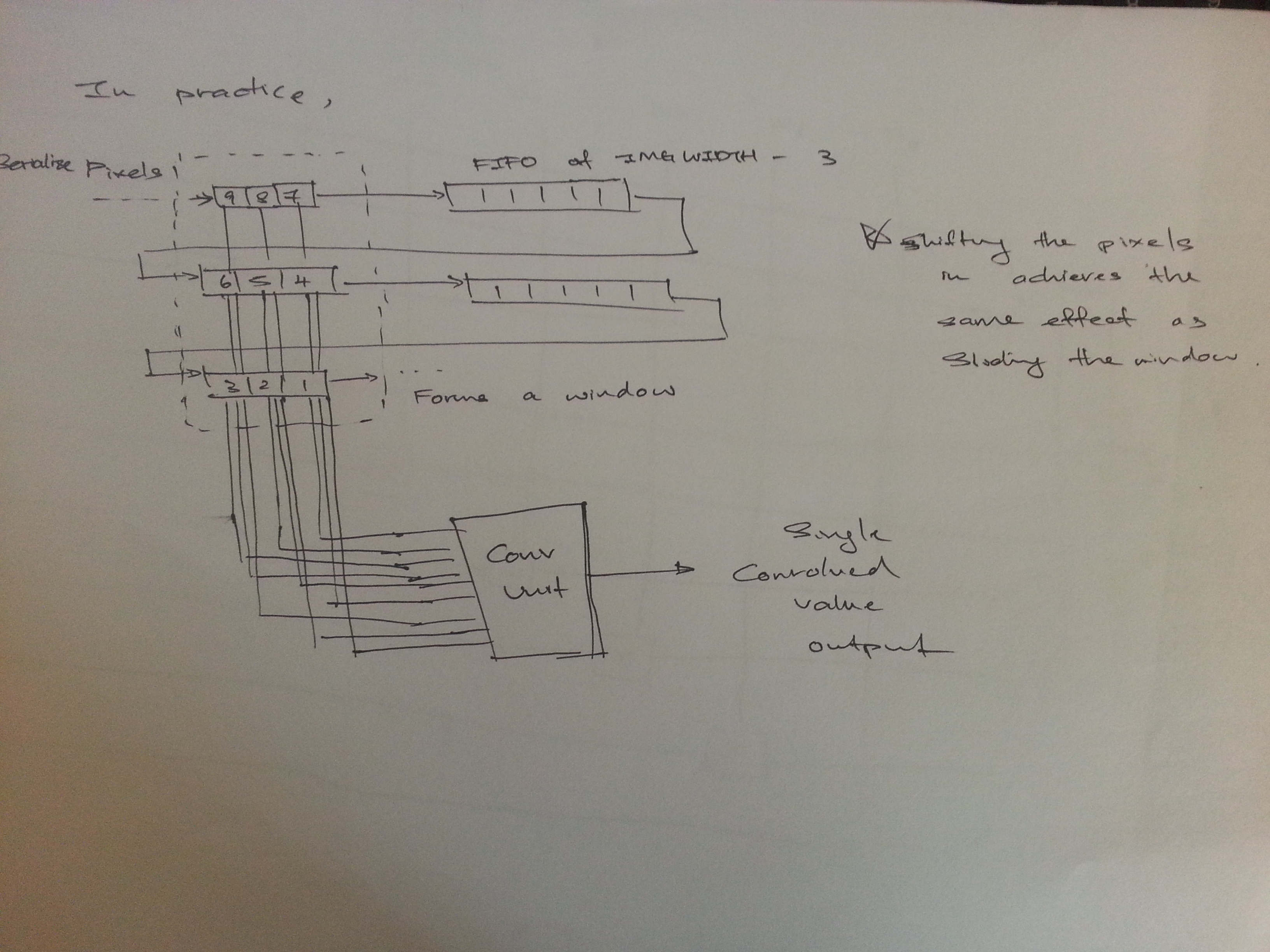
The first image shows the simplified idea of the entire process, whereas the second image shows the implementation of the sliding window in actualty.
You can see in this image that the 9 pixel data shifted in forms a 3x3 window. When implementing this, I included the FIFO as part of the window component so that the whole thing consist of only two components: the top part and the bottom part.
Filtering using a sliding 3x3 kernel
Actual Implementation
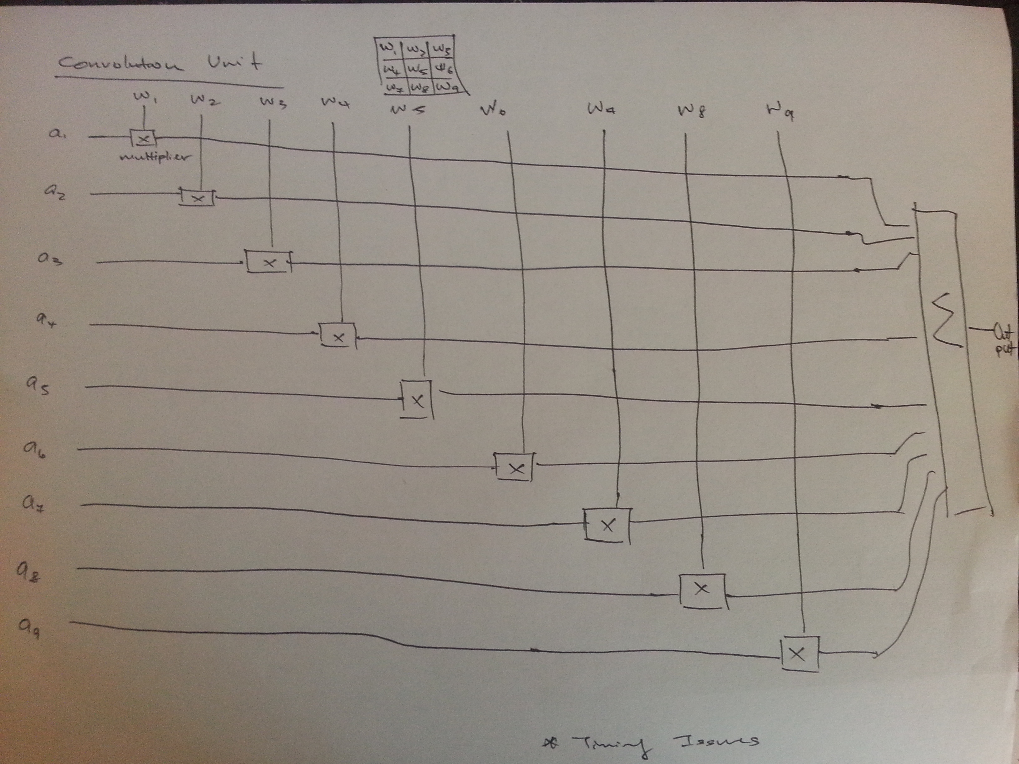
The third image shows the convolution unit. In practice, this doesn’t work 100% of the time and introduces some bugs due to timing constraints caused by the DSP components (much to my dismay). To avoid that, it is necessary to implement pipelining to perform the multiplication and summation by stages. You can look up on how to do pipelining easily in VHDL by googling for it or simply uses a (Finite State Machine) FSM and think of each operation as a state. My implementation uses a FSM.
Convolution Unit
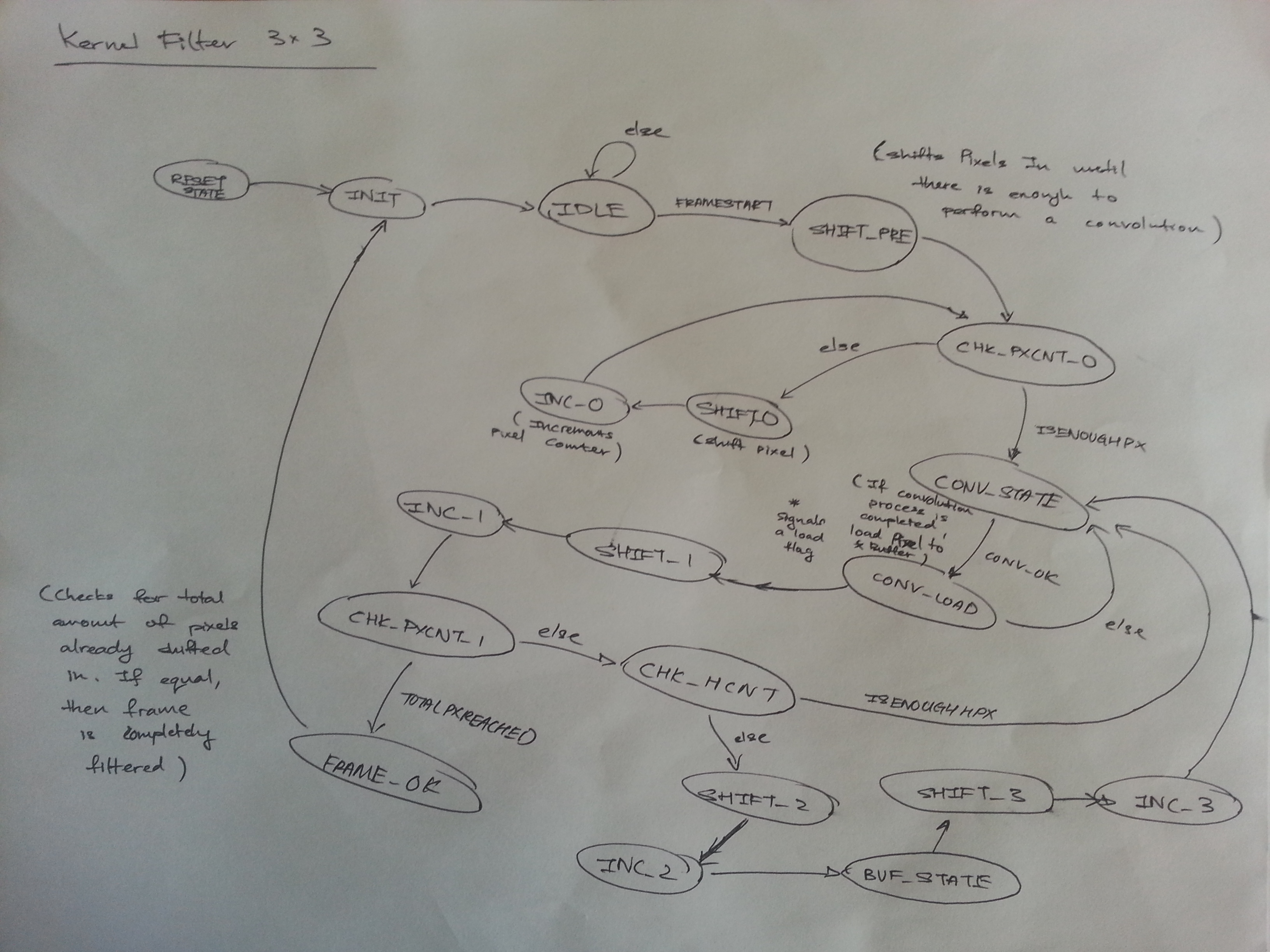
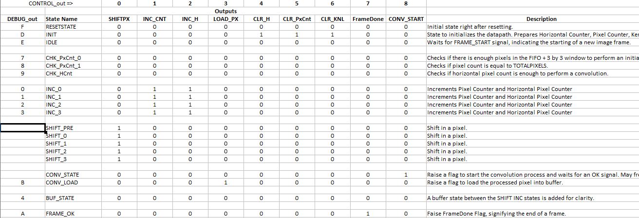
Filter Controller
The last two images show the FSM of the controller which figures out when to start processing, when convolve the pixels, when to roll over and when to finish.
Again, some of the states are redundant and can be combined but are seperated for clarity and easier implementation and debugging.
Do remember that each of the state uses up at least one clock cycle (if no loop), however, and thus introduces delays. If your specific application is a hard real time system (ie, you need the image to be filtered within a specific amount of time), then it might not meet the requirement of the system. The same thing can be said for the pipelining process of the convolution unit.
What you can do at this point is to either increase the clock frequency of the board and deal with a more stringent timing requirements, or come out with a quicker algorithm which requires less clock cycle to complete a full filtering process.